|
|



























HANDCARTZ.COM
Page 3
M1A1 CHEMICAL MORTAR & AMMUNITION CART
Page 3
FM 23-92
DEPARTMENT OF THE ARMY FIELD MANUAL
4.2-INCH MORTAR M2
APRIL 1951
Page 651
DEPARTMENT OF THE ARMY FIELD MANUAL
4.2-INCH MORTAR M2
APRIL 1951
Page 651
(Fig. 221). To replace the pull handle, reverse this
procedure.
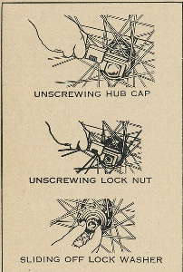
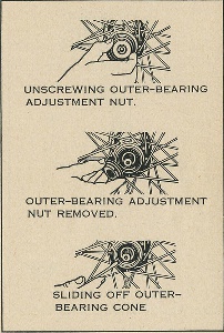
c. Wheel. Figure 222 shows the disassembly of the
cart wheel.
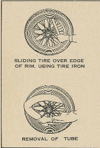
d. Tire. To remove the tire, first release the air from
the inner tube. Remove the lock nut on the valve and
apply the tire iron to lift the tire edge over the rim edge.
After the tire is completely lifted over the rim edge,
push the inner-tube valve into the space between the
tube and the rim. Reach in and pull out the inner tube
(Fig.223). Remove the inner tire flap.
e. Tool Box. To remove the tool box, remove the chassis.
Disconnect the screw-holding chain of the pole pin.
When this is accomplished, lift the box out of its posi-
tion. To replace the box, reverse this procedure.
5. MAINTENANCE
a. The pole and pole-pin socket, the tool box hinges
and latch, the coupling, and the mortar-barrel rack-
stake lock pins should be kept lightly coated with a
special preservative lubricating oil.
b. The wheel bearings should be greased at least twice
a year or after each deep-water fording. Clean the
grease fittings before greasing.
c. For painting, follow the procedure given in chapter
2/ paragraph 10.
6. OPERATION
a. To replace the load on the cart, proceed as follows:
(1) Put the pick-mattock head, gunner's tool roll,
mortar cart equipment, and oiler in the tool roll
box.
procedure.
c. Wheel. Figure 222 shows the disassembly of the
cart wheel.
d. Tire. To remove the tire, first release the air from
the inner tube. Remove the lock nut on the valve and
apply the tire iron to lift the tire edge over the rim edge.
After the tire is completely lifted over the rim edge,
push the inner-tube valve into the space between the
tube and the rim. Reach in and pull out the inner tube
(Fig.223). Remove the inner tire flap.
e. Tool Box. To remove the tool box, remove the chassis.
Disconnect the screw-holding chain of the pole pin.
When this is accomplished, lift the box out of its posi-
tion. To replace the box, reverse this procedure.
5. MAINTENANCE
a. The pole and pole-pin socket, the tool box hinges
and latch, the coupling, and the mortar-barrel rack-
stake lock pins should be kept lightly coated with a
special preservative lubricating oil.
b. The wheel bearings should be greased at least twice
a year or after each deep-water fording. Clean the
grease fittings before greasing.
c. For painting, follow the procedure given in chapter
2/ paragraph 10.
6. OPERATION
a. To replace the load on the cart, proceed as follows:
(1) Put the pick-mattock head, gunner's tool roll,
mortar cart equipment, and oiler in the tool roll
box.
Page 652
1
Figure 222. Disassembly of cart wheel.
Figure 222. Disassembly of cart wheel.
Page 653
2
Figure 222-continued.
Figure 222-continued.
Page 654
3
Figure 222-continued.
Figure 222-continued.
Page 655
4
Figure 222-continued
Figure 222-continued
Page 656
Figure 223. Removal of tube